S.Bus Basics
A quick overview of S.BUS in under 3 minutes.
-
PWM
The conventional way to connect a receiver and servos is to connect each servo to the designated receiver output channel depending on the role of each servo installed on the aircraft/vehicle (aileron, throttle, etc.).
As the number of channels required increases, so does the size of the receiver and the quantity of wires (with a corresponding increase in weight). The receiver output area can become crowded, making it difficult to arrange wires for a neat and tidy installation.
-
S.Bus
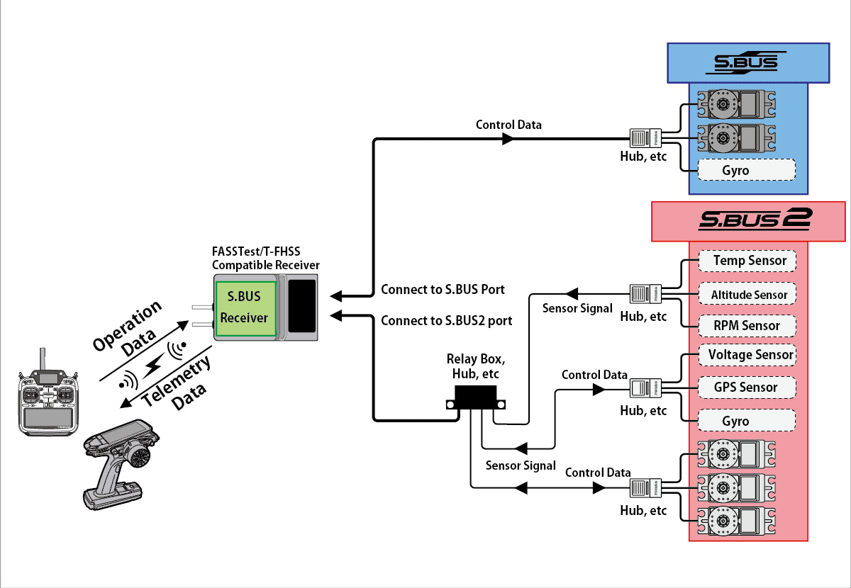
S.BUS was devised to eliminate the inconveniences found with the PWM system. It supplies control data for all channels to all servos, with each servo programmed in advance to determine which channel of control data it receives. Multiple servos can be connected to the receiver by simply connecting one control signal line, with each servo connected through a dedicated hub or relay box.
S.BUS is a monodirectional communication system for sending control data from the receiver to the servos.
-
S.Bus2
S.BUS2 is a two-way communication system that not only controls S.BUS2 servos but allows for sending data from telemetry sensors connected to the receiver back to the transmitter.
Receivers equipped with S.BUS2 such as FASSTest or T-FHSS, information such as the battery voltage, motor rotation speed, and temperature of the aircraft/car can be monitored on the transmitter’s display screen.
S.Bus Accessories
View allFine Print
S.BUS2
S.BUS2
Please note that if devices other than S.BUS2 compatible devices (including “S.BUS” servos) are connected to the S.BUS2 controlled line, the S.BUS2 devices will not operate properly.Therefore, connect only S.BUS2 compatible devices to the S.BUS2 system.
S.BUS/S.BUS2 is also employed in some drones and industrial apparatus besides hobby RC devices. Please do not connect devices that do not indicate the S.BUS/S.BUS2 logo as this may cause operational issues.


